
 contact
Behaviour of steel structures containing cracks
Department of Structures
The project is aimed to the extension of present knowledge of non-linear response of thin-walled steel structures which contain growing cracks. The process of deformation and degradation of the structures is studied by means of appropriate non-linear solution strategy and suitable model of a structural geometry including initial imperfections. Numerical simulations are based on elastic-plastic variant of finite-element method taking into account large deflection theory employing plate and/or solid elements when describing the cracks penetrating the thickness of thin-walled components.
The fundamental problem of numerical simulations of real structures inheres in proper estimation of out-of-plane bending stresses which are significantly affected by the initial deflection geometry of the components; inaccurate modelling of the geometry can lead to the different stress distribution, and so to different way of crack propagating. A change in the deflected shapes of the components with growing cracks under loading greatly complicate the non-linear solution. This with an inappropriate solution strategy may produce wrong results.
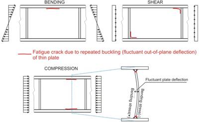
Figure 1: Cracked Structures made from thin steel plates. The plates are prone to buckling under in-plane bending, shear or compressive load. Near or excess of the buckling load, the plate deflections increase considerably. The large plate deflections induce high bending stresses on the plate surface at the boundary formed by attached flanges or stiffeners. If the load is reapplied a sufficient number of times the stresses may produce fatigue crack growing along the boundaries.
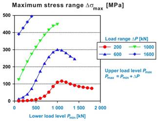
Figure 2: The envelope of maximum bending stress ranges (tensile values) obtained from the stress distributions calculated along the plate-to-flange connection. The structure exhibiting one variant of the initial plate deflection geometry is subjected to compression with various loading parameters. Simplified numerical model – geometric non-linearity only – has been applied. The figure shows that for the same load range, the largest stress range need not correspond to the largest loads.